nyu_torch.gif

Blog

Posts tagged physical computing
ICM and PCOMP Final: Santa's Zombie Boot Camp

This was a shared between project with Martin Martin and I. It was a Physical Computing final for both of us, and also an Computational Media final for me. This blog will focus on the ICM aspects of the project. For the PCOMP take on the project, visit Martin’s blog (link here)

Santa’s Zombie Boot Camp

p5 Sketch (link here)


This project was tough. I had an idea of what I wanted, and I didn’t think it would be too far from what we had for the midterm (link here) but I was wrong. I decided to remove the jump mechanic from the game because it didn’t make too much sense for our zombie to jump, and we added a Santa theme to the game which called for almost a complete redesign.

Getting the physical components together was frustrating, but not overly difficult. If anything it was just a little more time consuming. Thinking that most of the work would be on the physical side, we didn’t leave too much time for the coding. This was a mistake. I think with more time and less pressure, I may have been able to work my way out of coding challenges on my own. Luckily, we have people at ITP like Max Da Silva and Aditya Jain. They were immensely helpful in getting this game to the place that it is at.

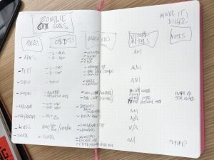
Something that helped this time was just making a list of my goals for the code. There were a lot of small tasks to accomplish, so having them laid out in a checklist helped me keep from feeling overwhelmed.

A List of Coding Goals for the game that breaks up the functions and addresses the general scope of the project

A List of Coding Goals for the game that breaks up the functions and addresses the general scope of the project

One of the issues that I ran into was getting the gifts to spawn when the Zombie got close enough to Santa. I was able to define the range in the code and even have it print “gift delivered!” every time the objective was met, but I couldn’t figure out how to make the pictures of presents show up a that point. Aditya helped me create an array for that and just clean up the experience overall.

Aditya also helped me figure out an issue with our start button and foot stomps. With my code, every time either of those sensors were activated, they would do so on the draw loop in a rapid-fire succession. I didn’t know how to get around that, so Aditya showed me how to use a throttle to have those sensors write once every second, which was key in having the game run properly.

Max helped us get the serial communication into our code. We had most of it there from our midterm, but we were having trouble with our gyroscope when we added it in. Max helped clean up our code to make that work.

Screen Recording of Santa’s Zombie Boot Camp

Alvaro playing Santa’s Zombie Boot Camp

P-Comp Paper Prototype!

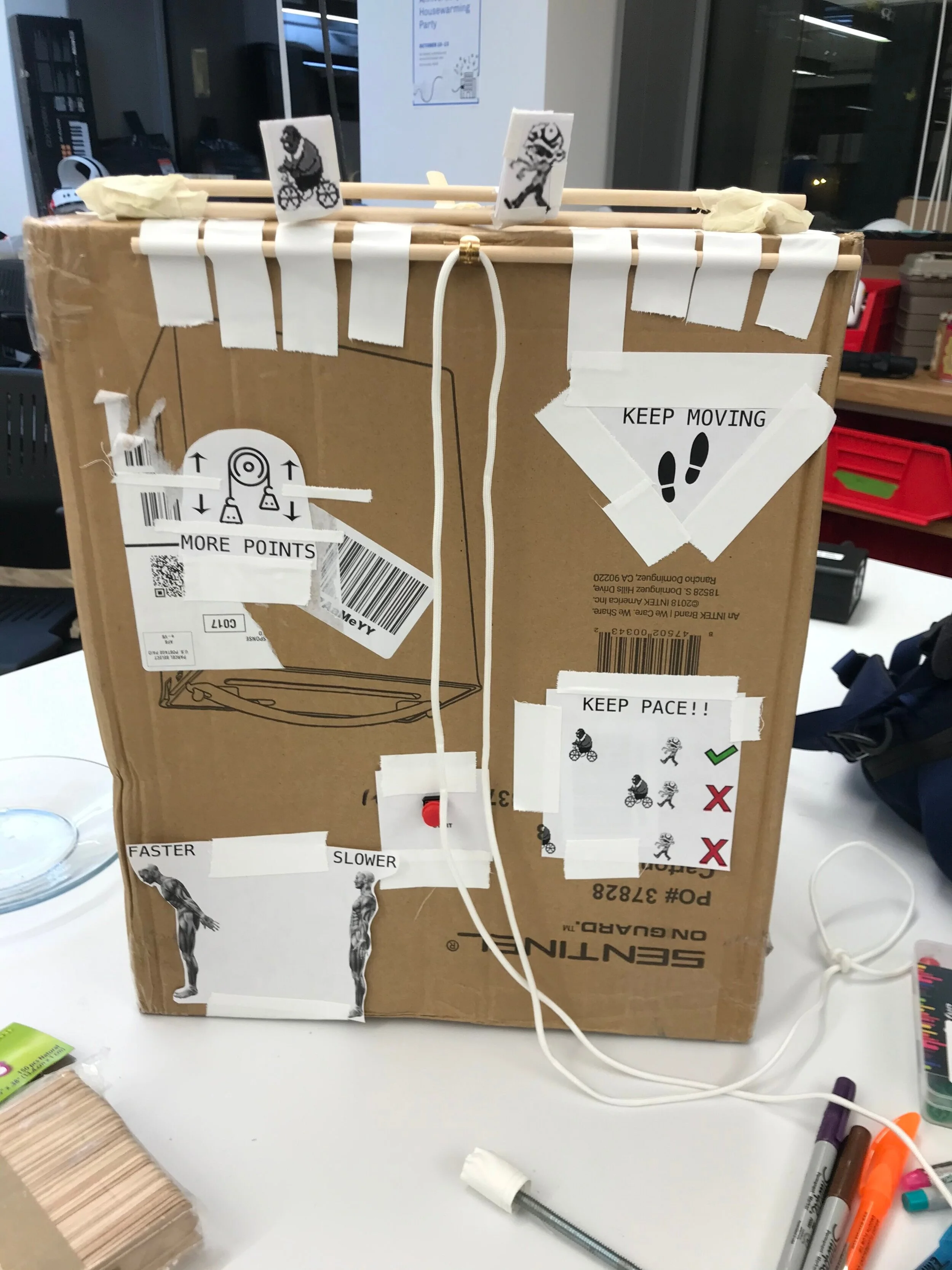
For our paper prototype we mocked up an analog version of our game.  Using a bunch of popsicle sticks, dowels, tape and printouts, we were able to replicate at least the bare idea of our game.  

This took a lot of thought and maybe assumption on our parts in order to figure out the best approach.  There were a few issues where we had differing opinions on how people would interact with the prototype.  We imagine that these issues will be resolved with the help of user testing that happens in class. 

To replicate the motion of the characters, we’ve used print outs on popsicle sticks that we’ll move based on the footsteps and the angle that the user is leaning. 

For the gyroscope, we’re thinking that something akin to a bolo tie that leaves the sensor close to the body would be most effective.  By placing the sensor behind the neck, and having the user tighten the tie, we can keep the gyroscope in place and keep the reading close to accurate. 

We’ve printed out instructions on how to play the game and tried to be as minimal as possible to avoid over-explaining.  We used icons with minimal language, hopefully that’s enough. 

Our prototype doesn’t reflect the actual position and spacing that we imagine the final product will have, but for the purpose of an analog version, we felt that this configuration would get us closer to the user experience. 

front+view+of+Zombie+Christmas+paper+prototype
footprint printouts for mock foot sensors
placement for mock gyroscope
how the bolo tie will work to secure the sensor
indicator showing that the player should go faster (the other side says slower with a red circle)
Physical Computing 10.17

This week, Martin and I discussed how to expand upon our midterm project, “Zombie Boot Camp” We got a lot of great feedback during the midterm when we showed our game.

  • Make it clearer that the player is controlling the Zombie

  • Make progress indicators so players know how much longer they have until the end and how well they are doing

  • Clean up the graphic movement (e.g. time jumps properly)

  • Fix music issues

We also came up with some ideas on a more immersive control experience. We’re very happy with the controller that we made for the midterm game, for the final, we’re thinking about how to create a standing arcade game. One idea that came up is the use of a large pad for the player to lean into with their chest to control the speed of the Zombie. The more they lean into it, the faster the Zombie goes, and the less they lean into it, the Zombie will slow to a stop. To prevent players from simply using the pad with their hands, there will be an added mechanic to the game that requires the players to keep their hands out in front of them. The idea would be that anyone who is playing the game is actually moving like a zombie. For the hands, we thought of buttons, hand loops (like on the subway trains), pulleys, or even blocks that would hang down and require the player keep them balanced on their hands.

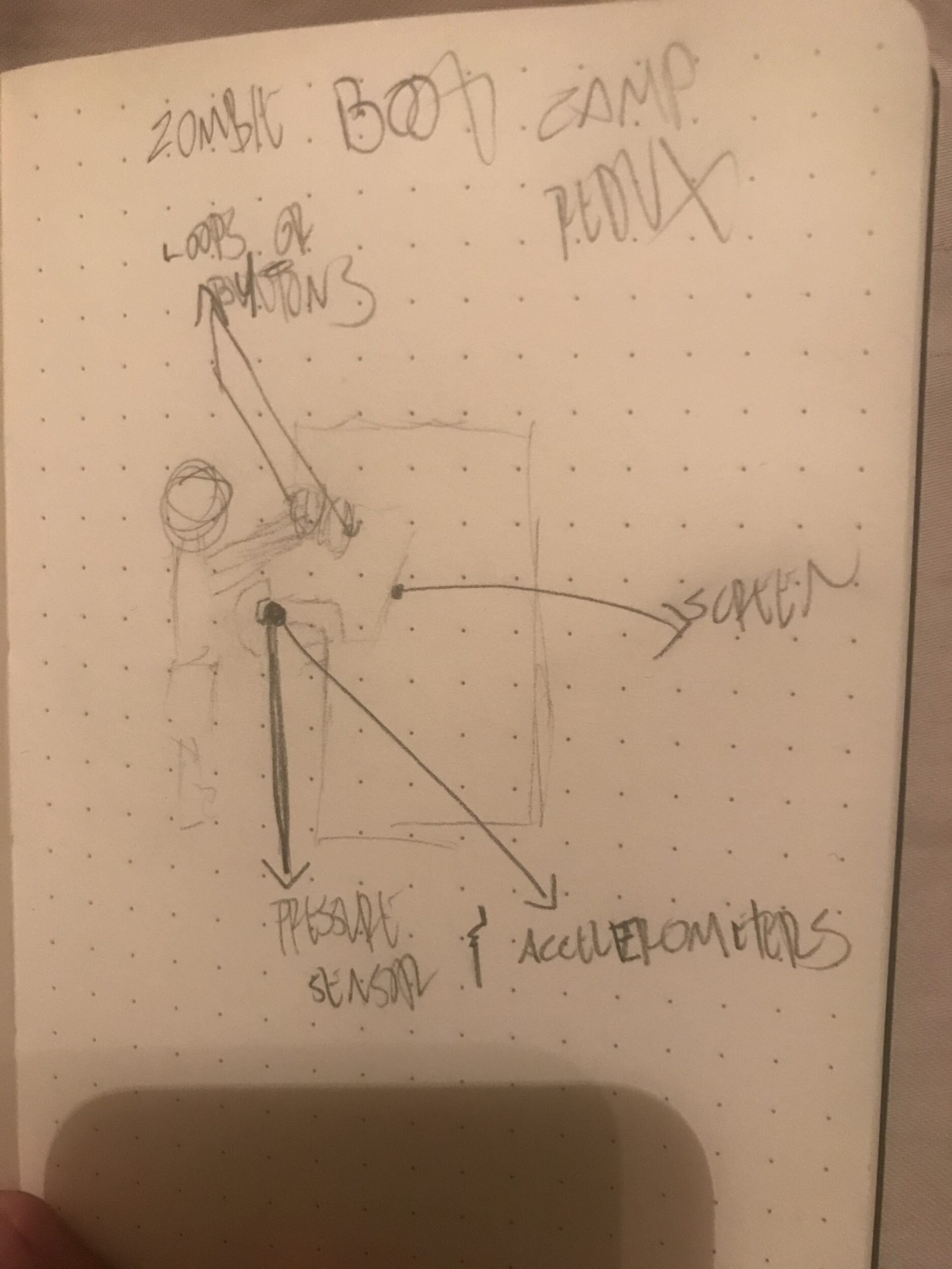
We’re still very much in the ideation phase, but it’s exciting to think about the possibilities. Here’s a rough sketch of what we had in mind at this point.

Rough sketch of what the “Zombie Boot Camp” arcade game could look like. There are indicators for a pressure sensor that the player would lean into with their chest. That sensor may also have accelerometers attached. The screen is marked where a tra…

Rough sketch of what the “Zombie Boot Camp” arcade game could look like. There are indicators for a pressure sensor that the player would lean into with their chest. That sensor may also have accelerometers attached. The screen is marked where a traditional arcade screen would be. There are also markings indicating that loops or buttons may be placed above/in front of the player to keep their arms busy.

Physical Computing 10.10

Serial Communication Labs

This week I worked on the labs with Martin and Nick. This was a much better way to work because we were able to bounce ideas off of each other and really try to fully grasp the concepts in a way that doesn’t happen as effectively when we work alone. A few highlights from this session is that we were able to use the inData property to control the color of our canvas (as seen below):

Using data from a potentiometer to control the background color of a p5 sketch

We also got the graph to work with the potentiometer as well. Overall these labs were super helpful in understanding how to get Arduino to interact with p5 and gave us some good ideas on how to approach our midterm.

using a potentiometer reading to generate a p5 graph

Project Ideas

Based on a current p5 sketch that I’m working on (link here) Martin and I were thinking about create a little Halloween-themed video game. We may use the “keep the pace” mechanic that I almost have done in the referenced sketch, we may do something slightly different. If we’re looking to stick with this idea, we’re thinking that we’d want to create a controller that consists of a potentiometer to control the speed of the character, and a button to potentially incorporate a jump function. We are in the process of determining win/lose conditions as well as penalties or bonuses for in-game actions. I feel like I’d be leaning pretty heavily on Martin for the p-comp stuff as I don’t feel too confident on that side.

Physical Computing 9.26.19

This week I was only able to get through the labs. The first lab had us connect a servo motor to the breadboard. I could see many uses for this, I just couldn’t quite wrap my head around a fun way to use it.

servo motor hooked up to breadboard controlled by a force sensitive resistor.

Next was a few different ways to hook a speaker up. Paulami helped me out with this, as I was having trouble understanding the diagram provided on the PComp site. She helped me with a barebones setup that allowed me to get a sense of how to make it work. I was surprised by how quiet the sound was, but it was super satisfying to hear it work. Later on Erkin showed me how a transistor could boost the volume up a bunch. When I make more time to work with this setup, I can see how it would be fun to create instruments with it.

Physical Computing 9.19.19

Button Switching between 2 LEDs

Working on the labs this week was very satisfying. We began work with the Arduino Nano. The first thing to know about this is that it is EXTREMELY hard to plug into the breadboard for the first time, so make sure that you have time to work it in there before you need to get started.

The first lab with the button to switch between the two lights went well. I had troubles initially because I only partially plugged my Arduino into the breadboard. I must’ve hit some halfway-type of plug-in because I was able to upload my initial code to the Arduino, but my second wouldn’t upload. When the second upload reached about 20 minutes in, I looked at the Arduino to realize that it wasn’t fully connected. SO MAKE SURE THAT YOUR ARDUINO IS FULLY PLUGGED IN!

Video of an Arduino on a breadboard connected to a button that switches between a red and a yellow LED when pressed.

Potentiometer controlling LED Brightness

Once I got that Arduino fully plugged in, things worked (obviously) a lot smoother. The next lab was to use a Potentiometer in an analog slot to control the brightness on an LED.

Video of an Arduino Nano connected to a breadboard that has a potentiometer controlling the brightness of a red LED.

Using the ideas from these two labs, I thought that it would be fun to create a game that worked on these fundamentals.

Rock Paper Scissors (FAIL)

The idea here was that I would take readings from two potentiometers, translate the readings from each into one of 6 values (rock1,, rock2 paper1, paper2, scissors1, or scissors2), create if/else statements to set conditions for winning and have it all hooked up to a button that, when pressed, lights up one of 3 LEDs to indicate where player 1 won, player 2 won or if there was a tie.

Close up of Arduino plugged into breadboard for RPS game

Close up of Arduino plugged into breadboard for RPS game

Another angle of the Arduino setup for the RPS game. There are two potentiometers, a button and 3 LEDs (two blue and one yellow) connected as well.

Another angle of the Arduino setup for the RPS game. There are two potentiometers, a button and 3 LEDs (two blue and one yellow) connected as well.

I ran the code from Labs 2 and 3 (mentioned above) to ensure that all of the components ran as expected. I was able to get the lights to respond to each potentiometer, and then when I changed the code I was able to get them all respond to the button. I was confident that I had everything set up on the board the way that it needed to be.

While writing the code, I figured that I would start by using Serial.println to test the values that I was getting from the potentiometers. This is where I realized that my logic was flawed. When getting a raw read of the signal coming from the potentiometer, I saw that I was getting a range of values from 0-1023. So I figured that if I break that range down into groups of 341 (1023/3), then I can designate each group to a value of either rock, paper, or scissors.

A screenshot of the code for the RPS game showing that the values from the potentiometer were split into 3 groups, rock, paper and scissors.

A screenshot of the code for the RPS game showing that the values from the potentiometer were split into 3 groups, rock, paper and scissors.

The problem, I theorize, is that the signal from the potentiometer isn’t stable enough to give a read that will allow the game to work. When I have the potentiometer on the lowest setting (0-341), it’s fine and shows a constant reading for scissors. The problem is that when I go into the higher ranges designated for paper and rock (341-682 and 682-1023, respectively), the reading bounces from what it’s supposed to be and scissors.

Serial Print values from the RPS code, note how there is never a constant Paper or Rock reading.

I think that if I were to continue this project, I would need something to smooth the signal coming out from the potentiometer, or I would need to use buttons instead. Either way, I feel that this was a great exercise and a successful failure in that I was able to push the limits of my knowledge.

Physical Computing 9.12.19

Introducing the 3-Card Monte Snitch-Switch!

Concept

This week’s assignment was to make a creative switch to light an LED using the kit that we received in class. In my initial brainstorm process I was coming up with really uninspired ideas. I didn’t really have much of a frame of reference to work from so I found it difficult to come up with anything. It’s like trying to imagine a color you’ve never seen, how do you even do that?

Luckily, ITP is full of people with ideas, so I hung out around the space and saw what people were working on. I saw Sam Krystal’s Gatorade bottle switch that activated by tipping the bottle over and having the liquid complete to circuit. Sylvan Zheng had a really advanced switch that was activated by the heat of a candle. Nikhil Kumar had a really fun switch that was fashioned after a basketball hoop with a ball made of foil. His idea is probably what helped me figure out how I wanted to approach this project.

My submission is called the 3-Card Monte Snitch-Switch. 3-Card Monte is a game, typically played as a gambling game in the streets. The person running the game has three playing cards. They show the player what the cards are and indicates which card the player should keep track of (usually an Ace or a Queen). The person running the game then proceeds to move and mix the cards up in hopes of making the player lose sight of where their card is at. When this is done, the player points to one of the 3 face-down cards and hopefully for them they get the target card.

My switch would let the player know which spot their card is in before it is turned up by lighting a corresponding LED light. Not really a practical device, but a fun project nonetheless.

Crafting

I used the breadboard for this project. Powering it with a DC Adaptor, I ran power and the ground along both sides of the board. I then added 3 resistors and 3 LEDs evenly spaced across the board. Instead of running power directly to each row with a resistor, I connected those rows to my “Snitch Board” where there were 3 pieces of foil for them to connect to. Also on the board was a longer strip of foil that ran the length of the 3 pieces of foil but did not come into contact with them. I ran the power from the side of the breadboard to this longer strip. The disconnect between these foil pieces is where the card game comes in.

Of the 3 playing cards, only one card, The Queen, had foil strips on the sides. I crafted a second layer to the Snitch Board that had grooves for the cards to slide into, and I covered those grooves in foil. Once the Queen came into contact with those grooves, the idea is that only the corresponding light would activate. I initially forgot to separate the pieces of foil on this top row which would have resulted in all 3 lights being activated without the card being inserted. Luckily I realized this error before I tape things together.

Results

The switch works, but not without issues. In my concept, one would be able to simply lay the cards on the board and have the light respond. In application, I actually have to push down on the card to activate the switch. I think I used too much electrical tape in the crafting and the grooves don’t allow enough allowance for the card to make proper contact.

If I were to attempt this again, I would consider using sturdier materials to put it all together. Wood could be nice. Cards may not be necessary, custom tiles with electrical contacts built into them could be a sleeker look.

This is the Queen card that completes the circuit with the aid of foil strips taped to the sides.

This is the Queen card that completes the circuit with the aid of foil strips taped to the sides.

This is the inside of the Snitch Board connected to the breadboard.  Here you can see where the power is designed to move between the two devices when the Queen connects the longer strip of foil to one of the smaller pieces.

This is the inside of the Snitch Board connected to the breadboard. Here you can see where the power is designed to move between the two devices when the Queen connects the longer strip of foil to one of the smaller pieces.

A demonstration of the 3-Card Monte Snitch Switch

Physical Computing 9.5.19

What is Physical Computing?

Since I’ve gotten accepted into ITP I’ve asked this question multiple times in a variety of forms. Within the program, what does it mean to focus on physical computing vs. more of the coding work? While registering for classes, what does the Introduction to Physical Computing class entail? On this first day of class, what is actual physical computing?

After my first day of class, I’m not quite sure that I have any form of an answer, at least not anything close to a satisfying answer. During the class discussion there were a few solid attempts at answers. There was talk of human-centered design, bridging the physical and digital worlds, intuition/pleasure/labor, and user experience (I would totally credit people who came up with these thoughts, but I’m still learning names, sorry!). These all seem to fall within the realm of physical computing, but I suspect that they don’t quite fully encapsulate the whole of it.

During a Paper Prototype exercise, I got a better sense of what Physical Computing might be. Working with Nick and Paulami, we came up with a prototype for a device that detected the freshness of milk, The Spoiler Alert! By thinking of how the device would work, how someone would learn to interact with it and how they would interpret the results from it, I was able to feel like this is what the class would be about. Due to the infinite variables within the prototyping process (available materials, various ways that people learn to navigate systems, various levels of comprehension, etc.) it is almost impossible to have a final product that is exactly as one would imagine it initially. When working with others, compromises will typically be made in order to come to a design that meets the standard of the group and not the individual. During the design process, I kept asking myself “Would I be able to figure out how to make this work if I wasn’t the one who designed it?” and that essentially became the driving force behind all of my input. It was great to have two other people to work with because it helped me understand how quickly my ideas translated to others.